
Wire Soldering 101: How to Solder Wires to a Circuit Board
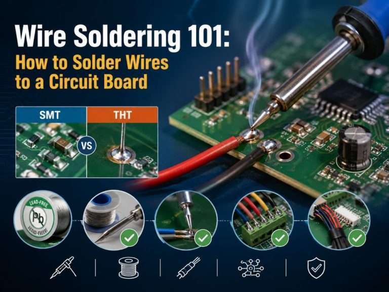
Soldering wire is the fundamental skill in electronics where wire to a Leiterplatte (PCB). And accuracy ensures reliable partnerships whether you are working professionally, settling a device, or putting together a do-it-yourself project. Thus, using a filler metal solder to unite two or more metal surfaces is known as soldering. In this blog, we will learn how to solder wire to circuit boards.
Types of Solder Wires
1. Lead Alloy Solder Wire
The most popular kind of solder wire, manufactured from metal lead, is regarded as the best. It often contains a combination of tin and lead. Because of its robust and consistent adhesion and bonding qualities, lead-based solder is the most commonly used type in electronics. It usually melts at 190°C and is made up of 40% lead and 60% tin. This shows how quickly it changes from a solid to a liquid.
2. Lead-free Solders
Lead-based solder wire remained the industry standard over time. However, the effects of lead on health brought about a change. This led to a significant decline in soldering wire’s selection and cost in a matter of years. Lead-free solder wire is made of copper, silver, and tin. Lead-free soldering wire is less costly than lead-based wire.
The melting point of lead-free solder wire is higher, ranging from 217°C to 221°C. It has aided in the reduction of small devices. A little board soldered with lead-free solder has a few issues. Compared to lead solder wire, they are superior.

Tools and Materials You’ll Need in Wire Soldering
- A soldering iron
- Lötdraht
- Wire strippers
- PCB and wire to be soldered
- A soldering stand or third hand
- Tweezers (optional)
- Isopropyl alcohol and a lint-free cloth for cleaning
- Optional insulation can be provided using heat-shrink tubing or electrical tape.
Step-by-Step Process to Soldering Wires
Step 1: Ready Your Workspace
First, you need to have a well-ventilated, and well-lit desk. Using a soldering tangle will safeguard your table and prevent small parts from rolling away. Because security is so important, work in an area with adequate airflow and consider using security glasses to protect your eyes.
Step 2: Prepare the PCB and Wire
- Inspect the PCB: Now, time to look for any solder pads or through-holes on the PCB. Use isopropyl alcohol to clean these ranges in order to stimulate elimination of clean, oil, or oxidation.
- Strip the Wire: Use wire strippers to expose a small portion of the wire’s conductor (almost 5-10 mm). Bend the strands together to prevent fraying in the unlikely event that the wire becomes stranded.
Step 3: Tin the Wire and Solder Pads
- Tin the Wire: Warm up your soldering press and touch the exposed wire with the tip. Apply a small amount of solder to the wire tip where it is in contact. The solder should cover the wire uniformly and smoothly.
- Tin the Pads: Use the tip of the soldering iron to apply a small solder to the PCB pad. You might only want a thin, glossy covering to guarantee a strong binding afterwards.
Step 4: Solder the Wire to the PCB
- Position the Wire: The wire should be placed on the pad that has been tinned. Use tweezers or a third hand to stabilize it if necessary.
- Apply Heat: Press the fastening press tip against the wire and the pad simultaneously. Remove it there for one or two seconds to warm them evenly.
- Apply Solder: Rather than applying the solder directly to the joint, apply it by feeding it onto it. The solder streaming should form a glossy, cone-shaped junction.
- Remove Heat: Remove the solder iron after the joint is created and let it cool properly. After relocating the wire, wait for the solder to set.
Step 5: Inspect Your Work
By glancing at the solder intersection, you can be sure it is clean and shining. A good intersection should look smooth and securely cover the wire and pads. If it is uninteresting or has holes, heat it up and add a tiny more solder.
Step 6: Add Insulation (Optional)
Protect any exposed wires close to the connection using heat-shrink tubing or electrical tape. This helps to keep unintentional short circuits at a safe distance.
Step 7: Test the Connection
Finally, use a multimeter to test the latched association to ensure progress. This attests to the wire and pads’ legal connection.
Machine Welding vs Manual Welding for Solder Wire
The two main techniques used in soldering to complete the exchange are machine welding and manual welding.
Manual Welding: The associations are made by skilled experts using a handy soldering tip. This strategy is ideal for intricate designs or intriguing endeavors since it provides exceptional flexibility and versatility.
Machine Welding: In machine welding, the fastening is done by automated machinery. This makes it unthinkably feasible for large-scale fabrication operations, when consistency and speed are crucial.
Wire Soldering Process for Different PCB Types
Because of their structural variations, single-layer and multi-layer PCBs require quite different soldering procedures.
Soldering For Single Layer PCB
Soldering techniques for single-layer PCBs are relatively straightforward due to their simple design. With components and traces confined to one layer, processes like wave soldering or manual soldering are commonly used.
These methods are efficient for the less complex layouts of single-layer boards and allow for quick assembly and rework if needed. The risk of overheating is minimal since there are no internal layers to consider, making single-layer PCBs easier to handle during soldering.
Soldering For Double Layer PCB
Im Gegensatz dazu, Mehrschichtige PCBs require more advanced soldering techniques due to their complex structure of interconnected layers. Reflow soldering is often the preferred method, as it ensures precise and uniform soldering without damaging internal layers.
Die Verwendung von Vias and advanced materials in multi-layer boards adds to the complexity, requiring specialized solder and flux to maintain reliability. Additionally, controlled heating profiles are crucial to prevent thermal damage and ensure strong, defect-free connections across all layers.
Different Types of Solder Pads
THT (Through-Hole Technology) und SMT (Surface Mount Technology) are the two primary types of solder pads, which are necessary for joining Komponenten to a PCB.
Strong mechanical bonding is provided by THT solder pads, which are perfect for heavy or high-stress components. These pads are made for components with leads that go through holes in the PCB and are soldered on the other side.
SMT solder pads, on the other hand, are flat and rest on the PCB surface. They are utilized for components that have short pins or no leads, allowing for smaller, lighter designs.
Soldering methods difference: SMT depends on precision methods like reflow soldering, which use solder paste and controlled heating to assure accuracy and efficiency, whereas THT frequently uses wave or hand soldering, which requires more solder to fill holes.
Mehr lesen: Difference between SMT and THT.
How to Troubleshoot Common Wire Soldering Problems
Cold Solder & Overheated Joint
One particular issue is a cold solder junction, where the solder does not follow well and seems grimy and unclean. This occurs when the component and pads are not sufficiently or evenly warmed. Conversely, overheated joints occur when the PCB or pads becomes overheated, which can lead to the pads lifting off the board.
Fixing: By using a fastening press with soldering temperature control and limiting the heat length, this may be prevented.
Bridging & Insufficient Solder
Another frequent problem is bridging, in which too much solder creates Kurzschlüsse between adjacent pads or pins. Lack of solder is another problem that results in a weak connection.
Fixing: To fix bridging, use a Lötdocht or pump to remove extra solder, being careful not to apply too much. Insufficient solder can be resolved by adding more solders while ensuring that the heat is communicated in a valid manner.
Oxidized Surfaces & Solder Balls
It is possible that solder will not adhere to soiled or oxidized surfaces. Cleaning with isopropyl liquor and using flux can greatly increase solder attachment. Solder balls, which are tiny beads that fail to set up appropriate intersections, are also frequently caused by rapid flux bubbling or uneven warmth.
Lifted pads can occasionally occur when the pads separate from the PCB as a result of extreme heat or rough handling. With careful soldering and appropriate temperature control, this may be expected. Misaligned components might also result from poor arrangement or development during fastening.
Fixing: To light oxide surfaces, regulate the heat and apply it fairly. Using tweezers or a third hand to hold components stable is considered as a direct settlement.
Are Solder Jumper Wires Important For PCB
The wire connecting two separate electrical circuits on the board is called a solder jumper wire. Also included are thick wires that join two circuits without the need for solder.
When linked, it may function as a circuit shortcut and result in a short circuit. Controlling the electricity on the board becomes feasible. So, boards that require less wiring can be controlled with solder jumper wires.
Solder jumper wires are available in a variety of colors. However, the color has little bearing on its application. Jumper wires are availiable in three modes, with two female ends, one female and one male ends, and with two male ends. They separate at the end of each. While the female solder jumper wire is primarily utilized for connecting, the male wire’s end protrudes.
Alternative Techniques for Attaching Wires to PCBs
Techniken | Vorteile | Beschreibung |
Terminal Blocks |
|
|
Steckverbinder |
|
|
Quick Fix Glue |
|
|
Oberflächenmontage-Technologie |
|
|
Reflow-Löten |
|
|
Safety Precautions During Solder Wire Process
Work in a Well-Ventilated Area
Ensure your workspace is well-ventilated to avoid inhaling fumes released during soldering, especially when using flux or lead-based solder.
Wear Protective Gear
Always wear safety glasses to shield your eyes from molten solder or flux splashes. And to protect your hands from burning, use heat-resistant gloves.
Avoid Direct Contact with Hot Tools
Never touch the soldering iron’s tip or heated components directly. Use tools like tweezers or clamps to handle parts.
Keep a Clean Workspace
Remove flammable materials from your work area to reduce fire risks. Maintain a tidy setup for safer soldering practices.
Use a Stable Soldering Iron Stand
Always place your soldering iron in a secure stand when not in use to prevent accidental burns or damage.
Unplug When Not in Use
When you finish soldering or take breaks, unplug the soldering iron to prevent overheating and accidents.
Wash Hands After Handling Solder
After soldering, wash your hands thoroughly, especially if you’ve used lead-based solder, to reduce exposure to harmful substances.
Fazit
It is important to comprehend the various methods of connecting wires to a PCB in order to design long-lasting and efficient electrical circuits. Depending on the specifications and requirements of your project, you can select the various soldering options. Additionally, the device’s functionality and quality can be significantly impacted by the kind of cable and connector you choose and how you connect them.
FAQs
For most modern PCB electronics, use lead-free rosin-core solder (e.g., SAC305: 96.5% Sn, 3% Ag, 0.5% Cu) with a diameter of 0.6mm (0.023″) to 0.8mm (0.032″). For hobbyists or where regulations allow, 63/37 tin/lead rosin-core (eutectic) is easier to work with and melts at a lower temperature.
The solder wire has a hollow core filled with flux. The flux cleans the metal surfaces (component leads and PCB pads) of oxidation, enabling a strong, reliable bond as you solder.
Fine work (SMD, tight spacing): 0.5mm – 0.6mm
General through-hole components: 0.7mm – 0.8mm
Larger connectors/wires: 1.0mm+
Using solder that’s too thick makes it easy to apply too much and cause bridges.
Lead-Based (Sn63/Pb37): Lower melting point (~183°C), easier to achieve shiny, reliable joints, better “wetting.” Used in hobbyist, aerospace, or medizinisch (where allowed). Requires proper ventilation and hygiene.
Lead-Free (e.g., SAC305): Higher melting point (~217-227°C), joints are duller, can be “grittier.” Required for commercial consumer goods by RoHS-Vorschriften. Needs a slightly hotter iron.
Typically, 2-3 seconds is sufficient. Prolonged heating (more than 3-4 seconds) can lift the copper pad from the PCB (delamination) or damage the component.
Angebot einholen
Verwandte Blogs
Table of Contents Design Rule Checking in PCB Design: From Altium DRC to SMT Assembly Published on September 10, 2024 · Updated on October 22,
Table of Contents Automotive PCB Assembly: The Complete 2026 OEM Guide Failure of a consumer good is a warranty claim. Failure of an automotive printed
Table of Contents Medical PCB Assembly: The Complete Guide for Medical Device OEMs Medical PCB Assembly is not a commodity process. It is a very
Table of Contents Drone PCB Design and Manufacturing: A Complete Guide for UAV Engineers This article was originally published in March 2024 and last updated
Table of Contents Security Camera PCBA Design Guide: Day/Night Switching and Infrared LED Driver Why Security Camera PCBA Design Matters for Day/Night Operation A security
Table of Contents AgTech Case Study: Manufacturing 2,000+ Agricultural Sensor Devices from Prototype to Production Designing an electronic prototype to large-scale production requires more than