
The Best Guide to Solar Inverter PCB

Understanding Solar Inverter
Let’s start by dissecting solar inverters if you want a more in-depth understanding of their circuit boards.
What is Solar Inverter ?
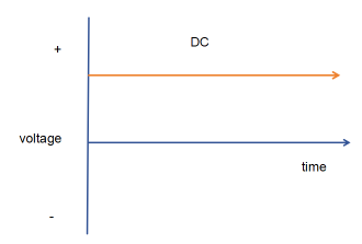
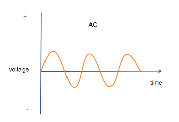
مورد | توضیحات |
|---|---|
Stability of output voltage | The battery will influence the process of charging and discharging, resulting in unstable voltage. There will be interval changes, to ensure the stability of the voltage and the output voltage fluctuation range of ± 10% |
Waveform distortion of output voltage | Usually expressed in terms of the total waveform distortion of the output voltage, the value of which should be no more than 5% (single-phase output is allowed to be 10%). |
Rated output frequency | Output frequency deviation should be within 1% |
Load power factor | The load power factor of the sine wave inverter is 0.7~0.9, and the rated value is 0.9. |
Inverter efficiency | The nominal efficiency of a mainstream inverter is between 80%~95%, and the efficiency of a small power inverter is required to be not less than 85%. |
Protection Measures | Under-voltage, over-voltage, over-current, short-circuit, reverse input, lightning protection, and over-temperature protection. |
نویز | The noise of the inverter should not exceed 80dB during normal operation, and the noise of the small inverter should not exceed 65 dB. |
How Does PV Inverter Work ?
So how exactly does an inverter work? Here are the exact steps:
- In grid-connected mode, the inverter connects the converted AC power directly to the grid to supply power to homes, businesses or large-scale power systems.
- In off-grid mode, the inverter stores the converted AC power in a battery for use in off-grid environments.
Let’s take a look at the solar inverter wiring diagram:

What is a Solar Inverter PCB Board ?
With a comprehensive understanding of solar inverters and how they work, it is easier to understand solar inverter PCB.
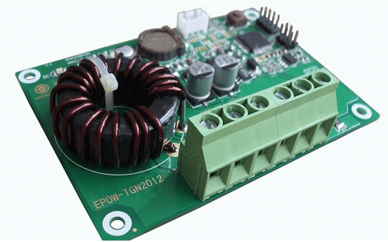
Solar Inverter PCBs Materials
Solar inverter PCB مواد are chosen based on high conductivity, thermal resistance, reliability, and environmental durability.
Base materials include
FS Tech considers application-specific requirements, including temperature range, mechanical strength, and cost, when selecting materials for solar inverter PCBs.
FR-4 is a cost-effective and widely used material for most solar inverter applications. However, for extreme conditions or special requirements, other materials such as PTFE or Polyimide may need to be considered.
Conductive Material
Copper is currently the most widely used material for connecting patterns of printed circuit boards due to its efficiency and relatively low price. Materials like gold or silver may be chosen especially for their increased conductivity or general corrosion qualities.
Solder Mask and Silkscreen
Such layers shield the components from being short-circuited. They also act as a channel for marking all the parts to enable the technicians to know which one is which when assembling or overhauling the equipment.
Types of Solar Inverter PCB
According to different technologies, inverters are mainly divided into: centralized inverters PCB, string inverters PCB, and microinverters PCB. At present, centralized and string inverters are the main types, and micro inverters are developing rapidly.
Types | توضیحات |
|---|---|
Centralized inverter برد مدار چاپی | Centralized inverter PCB, mainly used in large-scale ground power stations, has a voltage level of 315V, suitable for high-voltage grid connection. |
String inverter برد مدار چاپی | String inverter PCB, also known as distributed inverter PCB, is mainly applied in all kinds of barren hills, industrial and commercial or family rooftops, the scale of the power station is usually not large, and it is integrated into the national grid through full feed-in or residual power feed-in. |
Micro inverter برد مدار چاپی | Micro inverter PCB, mainly applied directly integrated into the battery board, is suitable for small family-type power stations. |
The other type is based on its application scenarios and functional requirements:
Types | توضیحات |
|---|---|
Standalone Solar Inverter برد مدار چاپی | This is an isolated system that draws DC power from the batteries you charge through your PV array. |
Grid-tied solar inverter برد مدار چاپی | This type will match the sine wave supplied by the utility, and for safety reasons, the inverter is designed to allow it to switch off automatically if you lose the utility supply. |
Battery Backup Solar Inverter برد مدار چاپی | This type will take energy from the batteries, manage the battery charge using an on-board charger and export the remaining energy to the grid. They can provide AC energy to specific loads during a power outage, and they require anti-islanding protection |
Intelligent Hybrid Solar Inverter برد مدار چاپی | These are modern and versatile inverters whose main operation is to consume the storage itself when it is used. This type manages the PV array, utility grid and battery storage within the unit. |
The third is categorized according to their power level.
Types | توضیحات |
|---|---|
Low Power برد مدار چاپی | This type of PCB is used in applications where power utilization is low. Such as small-scale projects. These projects include homes, small businesses, or portable containers. Low Power PCB can handle electrical loads less than 1 Kilowatt. |
متوسط قدرت برد مدار چاپی | This type of PCB is mostly used to power residential buildings and commercial offices. It offers an electrical load from 1 Kilowatt to 10 Kilowatt. |
High Power برد مدار چاپی | High Power PCB is used in applications where utilization of energy is high on demand. It can handle electrical loads from 10 Kilowatt to 100 Kilowatt. The main purpose of designing this PCB is to power large commercial and industrial setups. |
Ultra High Power برد مدار چاپی | Ultra High Power PCB is capable of managing an electrical load of more than 100 Kilowatt. PCB is used in large-scale projects. This PCB was designed using advanced design and manufacturing principles, which enhances the rigidness and durability of the PCB. |
The Significance of PCBs in Solar Inverters
The PCB acts as the structural foundation within solar inverters, connecting all the essential components of the inverter to make a robust assembly. They support all the critical electronic components required for the power conversion process.
These PCBs are designed to handle high currents, control heat and withstand environmental challenges.
Electrical Connections
PCBs enable a seamless connection between capacitors, diodes, and microcontrollers in inverters. This connectivity is crucial for smooth power flow and effective energy conversion. PCBs in solar inverters are designed to manage high-power currents generated by solar panels. This includes regulating energy flow in systems as varied as solar inverter circuit boards and solar inverter PCB boards, ensuring energy is processed efficiently with minimal loss.
مدیریت گرما
Solar inverters generate significant heat during operation, particularly in high-power systems like 600-watt inverter PCB with transformer models.
Thermal Design of PCBs:
PCBs in solar inverters are designed to optimize heat dissipation through carefully planned patterns and materials. Thus, providing stable temperatures during operation, preventing thermal stress on components, and ensuring reliable performance.
Heat Dissipation Strategies:
High-power inverters use advanced cooling solutions, including heat sinks and fan systems. It utilizes advanced strategies like multi-layer PCBs with improved heat dissipation properties. For instance, 200-watt inverter PCBs are equipped with copper layers to improve thermal conductivity, whereas larger inverters incorporate specialized heat dissipation elements.
قابلیت اطمینان و دوام
A major parameter also within solar inverter PCBs is the reliability which is impacted particularly when environmental ruggedness is vital. PCBs used in outdoor solar installations must use materials that cannot easily degrade when exposed to moisture, dust, and UV radiation.
انتخاب کردن FR4, polyimide, or metal-core substrates kept on PCBs responds to the demanding conditions of applying solar panels. These materials are quite popular in solar inverter PCB kits for improved durability. Further, one must investigate the external environment. Solar inverter PCBs are designed to work in moist environments, high levels of UV radiation, and temperature fluctuations. This reliability is especially important for circuit boards of solar inverters and complex systems with increased levels of dependability.
Components of Solar Inverter PCB
Key components on a solar inverter PCB include:
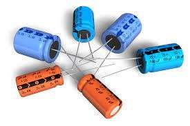
خازنها: They stabilize voltage by storing and releasing energy.
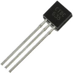
ترانزیستورها: Be used as power amplifiers and switches necessary for energy conversion.
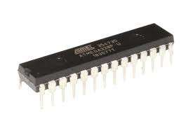
Microcontrollers: intrinsically control and coordinate the operation of an inverter and facilitate communication between components.
دیودها: Promote the concept of single-source current, prevent current backflow to other components, and therefore increase the system’s safety.

Factors Contributing Towards Solar Inverter PCB Failure
Failure of solar inverter PCBs can be attributed to various factors, such as:
Overheating:
Lack of proper thermal management may cause dangerous overheating, and a decrease in lifecycle, which is critical for high-power devices like PCBs of 600-watt inverters.
قرار گرفتن در معرض محیط زیست: Climate changes also affect the deterioration of PCB materials and failures of circuit boards of solar investors due to moisture or UV effect.
Manufacturing Issues: Defective soldering, low quality of the materials used, or poor quality control can make poor connections and or make PCBs fail prematurely.
Addressing Solar Inverter PCB Failures
Following preventive and corrective measures are required to address solar inverter PCB failures:
- Maintenance of heat sinks and fans lowers the chances of overheating immensely. Thus, providing enhanced thermal management
- Routine Inspections and maintenance help prevent corrosion and other environmental damage.
- Assuring that PCBs meet high standards of material quality and construction will greatly reduce failure rates.
How to Select a Solar Inverter PCB
To ensure the normal operation of the solar photovoltaic power generation system, the correct configuration of the photovoltaic inverter selection is very important. In addition, the configuration of the inverter should be based on the entire PV power generation system of the various technical indicators and refer to the manufacturer to provide a product sample manual to determine. Also, need to consider these indicators: the rated output power, the output voltage adjustment performance, the whole machine efficiency, and start-up performance.
In addition, the following factors need to be considered:
- Power Requirements: Select the correct power capacity PCB, a 200-watt inverter PCB for small applications, or a 600-watt inverter PCB with a transformer for large applications.
- Thermal Properties: Assure the PCB has adequate heat dissipation features to handle power loads without overheating.
- مقاومت محیطی: Look for materials and coatings providing resistance to moisture, UV exposure, and temperature fluctuations.
Tips for inverter pcb kit price:
1, 220V output voltage of the grid-connected inverter, generally applied to the family photovoltaic power station.
2, 380V output voltage grid-connected inverter, mainly used in the construction of various types of industrial and commercial rooftop power plants and many places in the country to the village as a unit of small centralized power plants.
3、Grid-connected inverters with 480V output voltage are mainly used in 10KV medium voltage grid-connected deserted mountain and beach power stations.
Future Trends and Developments
Future PV systems will evolve toward a more integrated approach, incorporating inverters, battery management systems, intelligent controls, etc. to form an integrated energy management system. Intelligent will also be highly developed to achieve network fault detection, remote monitoring and optimization control.
Advances in technology are reshaping PCB design for solar inverters, focusing on smart functionalities and energy storage compatibility:
Future PCB will allow solar inverters to connect with the grid and improve energy dispatch.
The PCBs will also evolve as energy storage systems grow, allowing electricity to be consistently stored and delivered from renewable sources like solar at any one time. This will determine the future of renewable energy systems with increased efficiency, reliability, and performance of solar inverters.
Efficiency improvement of PV inverters is one of the key goals for future development. By optimizing the inverter design, adopting new semiconductor materials (e.g. SiC, GaN), and advanced control algorithms, the losses during energy conversion can be reduced and the overall system efficiency can be improved.
PV systems are developing in the direction of integration, integrating components such as inverters, battery management systems (BMS), and intelligent controls to form an integrated energy management system. This integrated design can simplify system installation and maintenance, and improve the overall performance and reliability of the system.
Intellectualization is an important direction in the development of PV inverters. The maintainability and user-friendliness of the system can be improved by realizing networked fault detection, remote monitoring, and optimized control. Intelligence can also optimize energy management and predictive maintenance through data analysis and machine learning technology to improve the operational efficiency and reliability of the system.
Optical storage and charging integration is one of the leading directions for the future development of PV inverters. This integrated system can simultaneously realize solar power generation, energy storage, and charging functions, improving energy utilization efficiency and flexibility.
Technological advances are driving changes in solar inverter PCB design, focusing on smart features and energy storage compatibility. This includes the adoption of higher-performance electronic components, optimized circuit layouts, and increased circuit integration to meet the future needs of PV inverters in terms of efficiency, intelligence, and integration.
نتیجهگیری
Solar inverter PCBs are the foundation of converting energy in both mini and large ways such as mini-inverter printed circuit boards to 600-watt inverter PCB with transformer type. They help to have continuous power flow, manage excess heat, and protect against the environment separately to produce reliable solar power. Thus, PCBs in solar inverters will remain dynamic seeing that these technologies are advancing with time and therefore will support the introduction of a sustainable and efficient energy system.
ما دوست داریم از شما بشنویم
وبلاگهای مرتبط
Table of Contents Design Rule Checking in PCB Design: From Altium DRC to SMT Assembly Published on September 10, 2024 · Updated on October 22,
Table of Contents Automotive PCB Assembly: The Complete 2026 OEM Guide Failure of a consumer good is a warranty claim. Failure of an automotive printed
Table of Contents Medical PCB Assembly: The Complete Guide for Medical Device OEMs Medical PCB Assembly is not a commodity process. It is a very
Table of Contents Drone PCB Design and Manufacturing: A Complete Guide for UAV Engineers This article was originally published in March 2024 and last updated
Table of Contents Security Camera PCBA Design Guide: Day/Night Switching and Infrared LED Driver Why Security Camera PCBA Design Matters for Day/Night Operation A security
Table of Contents AgTech Case Study: Manufacturing 2,000+ Agricultural Sensor Devices from Prototype to Production Designing an electronic prototype to large-scale production requires more than