
目次
The Complete Guide to HDMI RF Modulators: Working Principle, PCBA Design, Installation, and RoHS-Compliant Manufacturing
This article was originally published in May 2024 and last updated on July 12, 2026.
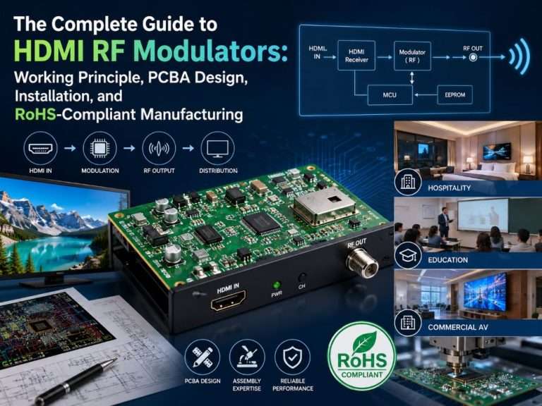
HDMI RFモジュレーターとは?

HDMI RFモジュレータの機能コンポーネント
- 入力インターフェース:ソース機器からのHDMI信号をモジュレーターに接続する場所です。通常、HDMI入力ポートが含まれる。HDMI traces must be routed as controlled-impedance differential pairs (100Ω) with strict length matching to maintain signal integrity at high data rates.
- エンコーダーHDMIからのデジタル音声信号と映像信号をRF伝送に適したフォーマットに変換し、変調の準備をします。The encoder IC is often a fine-pitch BGA package, demanding precise はんだペースト印刷, reflow profiling, and X線検査 to avoid head-in-pillow defects.
- 変調器:エンコードされた信号を特定の無線周波数に変調し、同軸ケーブルでの伝送に備える。RF sections require 75Ω controlled impedance for the output traces, plus careful grounding and shielding to prevent phase noise and spurious emissions.
- 電源:内蔵電源または外部アダプターにより、動作に必要な電力を供給。Switching regulators can inject noise into sensitive RF circuits; proper filtering and PCBレイアウト isolation are essential.
- チャンネル割り当てコントロール:変調信号に特定のRFチャンネルを割り当てることができ、RFチューナー付きテレビへの送信が容易になる。User interface elements (buttons, displays, or digital interfaces) must be placed away from RF paths to minimise interference.
- 出力インターフェース:変調されたRF信号が出力される場所で、通常は同軸ケーブルで接続される。The connector footprint and launch geometry must be designed for 75Ω characteristic impedance to avoid reflections.
- ユーザーインターフェース:変調器の中には、物理的なボタンやディスプレイ画面、あるいはコンピューターやモバイル機器からアクセスできるデジタルインターフェースなど、設定や設定を調整するためのインターフェースを備えているものがあります。
Classifications of HDMI RF Modulators
Based on Modulation Type
- Analogue Modulators – Convert HDMI into legacy analogue RF signals (e.g., NTSC/PAL). Suitable primarily for older TV systems that lack digital tuners.
- Digital Modulators – Encode and modulate the signal according to digital standards (for example, ATSC, DVB-T, or ISDB-T). The superior picture quality, high spectrum efficiency, and ability to transmit HD content are among their benefits.
Based on Channel Number
- Single-Channel Modulators – Accept one HDMI input and output a single RF channel. Good for small applications like home theatres, small offices, or single-room setups.
- Multi-Channel Modulators – Accept multiple HDMI inputs and produce several RF channels at once. Designed for large-scale applications such as hotels, hospitals, and campuses where many different sources must be distributed to many displays.
How Does an HDMI RF Modulator Work?
- 配給: 現行の同軸ケーブルを使用して、複数のテレビにHDMI信号を長距離伝送。
- コストと設置: セットアップの簡素化と reduce costs compared to running multiple HDMI cables.
- 品質だ: 高品位オーディオおよびビデオ伝送をサポート。
- 柔軟性: RFチャンネルを割り当てて配信をカスタマイズ。
- 統合だ: 既存のAVシステムに簡単に統合できます。
What is an HDMI RF Modulator Used For?
- ホスピタリティだ: ホテル、モーテル、リゾートは、高品質のオーディオビジュアル・コンテンツを利用できる客室内エンターテインメントを宿泊客に提供している。
- エンターテイメント会場 スポーツバーやレストランなどでは、多数のテレビに複数のイベントやチャンネルを同時に表示する。
- 教育機関: 学校、カレッジ、大学では、教育用ビデオ、プレゼンテーション、教室でのアナウンスなどに変調器を使用します。
- 企業設定: オフィスや会議室では、プレゼンテーションやビデオ会議、全社放送にモジュレーターを活用し、社員間のコミュニケーションやコラボレーションを強化しています。
How to Install an HDMI RF Modulator?

HDMI RFモジュレーターを取り付けるには、以下の洗練された手順に従います:
モジュレーターの取り付け ソースデバイス(ケーブルボックスやメディアプレーヤーなど)と、建物内のケーブルインフラの両方からアクセス可能な場所を選びます。一般的には、ソース機器に近い壁やラックで、同軸ケーブルインフラにアクセスできる場所の近くです。適切なハードウェアを使用して、HDMI RFモジュレーターを選択した場所(壁またはラック)にしっかりと取り付けます。安定性があり、将来の調整やメンテナンスのために簡単にアクセスできることを確認してください。
ソース機器の接続 高品質のHDMIケーブルを使用して、ソース機器(ケーブルボックスなど)を変調器のHDMI入力ポートのいずれかに接続します。
同軸ケーブル・インフラへの接続: 同軸ケーブルの一端をHDMIモジュレーターのRF出力ポートに接続します。もう一方の端は、ビルやセンターの既存の同軸ケーブルインフラに接続します。
変調器への電源供給: モデルによっては、内蔵電源または外部電源アダプターのいずれかを使用して変調器に電源を供給します。信頼できる電源に接続されていることを確認してください。
変調器の設定: コントロールやユーザーインターフェースからモジュレーターの設定にアクセスします。チャンネル割り当てや変調タイプなど、特定のニーズに応じて設定を行います。お使いのモジュレーター・モデルに合わせた詳細な手順については、メーカーのマニュアルを参照してください。
セットアップのテスト 変調器に割り当てられたチャンネルにテレビを合わせて、設置を確認する。映像と音声の品質が期待通りであることを確認します。必要に応じて設定を微調整し、パフォーマンスを最適化する。
ケーブルの固定とラベリング: Use appropriate cable management techniques to secure all cables. Label the HDMI RF modulator and associated cables for easy identification during future maintenance or adjustments.
メーカーのマニュアルを参照する: 具体的な内容については トラブルシューティング ヒントを得るには、HDMI RFモジュレーターに付属しているメーカーのマニュアルを参照してください。このマニュアルには、モデル固有の説明とガイドラインが記載されています。
これらの最適化された手順に従うことで、HDMI RFモジュレーターの信頼性の高い効率的な設置が保証され、将来の使いやすさとメンテナンスの両方が向上します。
RoHS Compliance in HDMI RF Modulator PCBA

How RoHS Compliance Affects PCBA Manufacturing for Modulators
- Reflow profile optimization – Accurate ramp-to-soak and reflow profiles allow avoiding voids in BGA-packaged encoder and modulator ICs, thus preventing thermal stress that may cause cracking of dielectrics or filter responses change.
- Prevention of tin-whiskers - コンフォーマルコーティング is applied on fine pitch areas, while connectors are coated with annealed pure-tin finish in order to minimize internal stresses and prevent whiskers growth.
- Post-assembly RF verification – All RoHS-compliant PCBA assemblies go through the spectrum analysis and return-loss tests in order to ensure that material changes did not impact channel power, adjacent-channel rejection, and MER parameters.
Verifying RoHS Compliance for Your Modulator
- Request full material declarations – In addition to final product assembly, material declarations should be provided for such critical RF components as PLL ICs, modulator chips, and connectors. Counterfeits are widespread in the RF industry.
- Check for IEC 62321 test reports – Third-party test reports verify that no restricted substances exceed the permissible limit for each homogeneous material.
- Look for clear markings – RoHS‑compliant products will have either the CE mark (for EU) or label “RoHS” on the packaging and product specification sheet.
What to Consider when Choosing an HDMI RF Modulator
これらの要素をこの順番で考慮することで、ニーズに合ったHDMI RFモジュレーターをより適切に選択し、さまざまなアプリケーションで最適なパフォーマンスを確保することができます。
互換性:
- モジュレーターが、接続予定のすべてのソース機器に対応していることを確認してください。
- これらのデバイスの解像度、フォーマット、オーディオ規格に対応していることを確認してください。
出力解像度とビデオ品質:
- 最高の視聴体験を保証するために、1080pや4Kなど、希望する出力解像度をサポートする変調器を選択します。
- 変調器が高品質のビデオ出力を提供することを確認してください。
遅延と同期:
- オーディオとビデオ間の顕著な遅延を避けるために、変調器が最小限のレイテンシーを導入するようにしてください。
- これは、ライブ放送やビデオ会議のようなリアルタイム・アプリケーションでは特に重要である。
ポート数
- RFモジュレーターで使用可能なHDMI入力ポートの数を確認してください。
- すべてのデバイスを同時に接続できる十分なポートがあることを確認する。
汎用性と拡張性:
- マルチチャンネル出力、リモートコントロール、ファームウェアのアップグレードなど、複数の機能をサポートしている変調器を選びましょう。
- 将来の追加や要件の増加に対応できるよう、デバイスの拡張性を考慮する。
放熱と耐久性:
- Understand the modulator’s heat dissipation design to ensure it doesn’t overheat during extended use.
- 特に業務用や需要の多い環境で使用する場合は、耐久性の高い機器を選ぶこと。
アフターサービスとサポート:
- アフターサービスやテクニカルサポートが充実しているブランドを選び、必要なときにサポートを受けられるようにしましょう。
- 保証条件を理解し、保証期間中の問題が効果的にカバーされるようにする。
PCBA Manufacturing Challenges for HDMI RF Modulators
- シグナル・インテグリティ – High‑speed differential pairs (HDMI) should be routed with proper impedance matching (100Ω) and low crosstalk; RF traces have to feature 75Ω impedance to avoid reflections and power dissipation.
- EMI/EMC Shielding – Absent adequate grounding and shielding, digital interference could be easily transferred to the RF section, negatively affecting modulation performance and leading to spurious emissions.
- Fine‑pitch Component Assembly – Contemporary modulators employ BGA-packaged encoder ICs and QFN modulators, demanding accurate solder paste printing, reflow profiling, and AOI/X‑ray inspection.
- アドバンスト プリント基板製造 – multilayer boards with controlled impedance stack‑ups, available from 4 to 12 layers.
- Precision SMTアセンブリ – fully automated lines with ±0.05mm placement accuracy, supporting 01005 components and 0.4mm pitch BGAs.
- Comprehensive testing - in‑circuit test (ICT), flying probe test, and custom RF 機能試験 to verify signal quality and channel performance.
- RoHS‑compliant materials – all soldering and 基材 meet EU and global environmental standards.
Why Partner with a Professional PCBA Manufacturer for HDMI RF Modulators?
- Faster Time to Market – プロトタイプ and volume manufacturing capabilities at one location make for an efficient supply chain.
- 品質管理 – A stringent quality control system (ISO 9001, IATF 16949) assures you get consistently produced product.
- スケーラビリティ – Easy move from プロトタイピング to high volume manufacturing as demand increases.
グローバル展開を加速する
信頼性の高いPCBAを使用
One-stop solution: PCB fabrication, sourcing, SMT assembly, testing & global logistics.
迅速な対応、厳格な品質管理。.
結論
よくある質問 (FAQ)
Partner with us & Start your PBCA Project
関連ブログ
Table of Contents Medical PCBA Cost in 2026: What Really Drives the 2.5–4× Premium Over Commercial Boards Medical PCBA costs do not only depend on
Table of Contents PCBA Functional Testing (FCT): A Complete Guide to Ensuring Board Reliability Published on May 9, 2023 · Updated on November 6, 2026
Table of Contents IPC Class 2 vs Class 3: Acceptance Criteria, Cost Impact, and How to Choose IPC Class 2 and Class 3 are the
Table of Contents Ventilator PCB Assembly: ISO 13485, IPC Class 3 & FDA QMSR-Ready Manufacturing Published on June 24, 2022 · Updated on October 30,
Table of Contents Ventilator PCB Assembly: ISO 13485, IPC Class 3 & FDA QMSR-Ready Manufacturing How is air delivered steadily with the help of ventilators,
Table of Contents Design Rule Checking in PCB Design: From Altium DRC to SMT Assembly Published on September 10, 2024 · Updated on October 22,