
High-Speed Serial Bus (GMSL/FPD-Link) Layout for ADAS Controller PCBA

High-Speed Bus Architecture in ADAS Explained
The Foundation: Transmission Line Impedance and Material Selection
Why Low-Loss Materials Matter
Critical Differential Pair Routing: Intra-Pair and Inter-Pair Matching
Controlling Intra-Pair Skew (< 5ps)

Inter-Pair Matching for Camera Arrays
Layer Transitions: Mastering Via Stub Control and Back-Drilling
The Danger of Via Stubs

The Solution: Controlled Back-Drilling

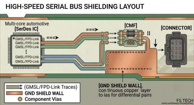
Automotive EMC Compliance: EMI Suppression and Shielding
Strategically Placing Common-Mode Filters (CMF)
Shielding the Connector Interface
ISO 26262 Functional Safety: Redundant Power and Monitoring
Power delivery redundancy and coax isolation

Continuous Voltage and Diagnostic Monitoring
10-layer Automotive Stackup Architecture
| Layer Number | Type of Layers | Main Functionality And Routing Rules |
| Layer 1 (Top) | Indication / Parts | High-speed connectors, passive components, IC breakouts. |
| Layer 2 | Plane | Reference plane of solid digital ground (gnd). Not at all split. |
| Layer 3 | Signal | High-speed GMSL / FPD-Link. Differential Routing Channel 1 |
| Layer 4 | Plane | Solid digital ground (GND) or clean power plane. |
| Layer 5 | パワー | Power rails that are segmented heavily. |
| Layer 6 | Power / Signal | Signals for control based on low-speed and diagnosis traces |
| Layer 7 | Plane | Solid Digital Ground (GND) reference plane. |
| Layer 8 | Signal | Channel 2 of a GMSL / FPD-Link to route differential signalling |
| Layer 9 | Plane | Reference plane of solid digital ground. |
| Layer 10 (Bottom) | Signal / Static | Networks and additional components of PoC filters. |
Best Practices for Stack Design
- Orthogonal Routing: Signal layers (e.g., Layers 3 and 8) must be routed orthogonally (perpendicularly) to adjacent layers to eliminate vertical broadside crosstalk.
- Core/Core Symmetry: Match the thickness of the prepregs and cores on the top and bottom halves of the board to prevent warping.
- Ground Planning: Dedicate layers to solid planes for shielding and low-inductance return paths.
結論
グローバル展開を加速する
信頼性の高いPCBAを使用
One-stop solution: PCB fabrication, sourcing, SMT assembly, testing & global logistics.
迅速な対応、厳格な品質管理。.
FAQs about Automotive ADAS Controller PCBA
- The dielectric constant of standard FR-4 (a component likely constructed out of copper clad) has been confirmed to be quite stable. When transmitting data, losses cause attenuation of the signal itself, rounding of digital switching edges and unpredictable phase skew. FR-4 highly degrades signals at high data rates (6 Gbps to 12 Gbps+). To ensure clear eye diagrams over long distances, the $$D$$ of low-loss materials used in the high-speed ADAS controller must be less than 0.004.
- The positive and negative lines of a differential pair can develop a mismatch in physical length, which is known as intra-pair skew. Trace corners and component breakouts frequently produce this effect. In order to compensate, designers add delay-matching structures (“bumps”) to the shorter trace. The bumps need to be positioned as closely as possible to the exact location of the mismatch. Furthermore, the bumps must have a loose high-radius geometry to avoid localized drops in impedance.
- As a high-speed signal transitions from a top layer to an inner layer through a via, the residual un-routed part of the via down to the bottom layer forms a “stub.” This stub acts like a resonant transmission line that can trap signal energy at some frequency, which forms a very severe notch filter in the Insertion loss profile. The excess copper stub is removed through Back-drilling by using a larger drill bit, which eliminates the reflections and resonances.
FSテクノロジーと提携して、プロフェッショナルなPCBAサービスを手に入れましょう。
関連ブログ
Table of Contents Medical PCBA Cost in 2026: What Really Drives the 2.5–4× Premium Over Commercial Boards Medical PCBA costs do not only depend on
Table of Contents PCBA Functional Testing (FCT): A Complete Guide to Ensuring Board Reliability Published on May 9, 2023 · Updated on November 6, 2026
Table of Contents IPC Class 2 vs Class 3: Acceptance Criteria, Cost Impact, and How to Choose IPC Class 2 and Class 3 are the
Table of Contents Ventilator PCB Assembly: ISO 13485, IPC Class 3 & FDA QMSR-Ready Manufacturing Published on June 24, 2022 · Updated on October 30,
Table of Contents Ventilator PCB Assembly: ISO 13485, IPC Class 3 & FDA QMSR-Ready Manufacturing How is air delivered steadily with the help of ventilators,
Table of Contents Design Rule Checking in PCB Design: From Altium DRC to SMT Assembly Published on September 10, 2024 · Updated on October 22,