Table of Contents

SMT vs THT: Differences between SMT and THT in PCB Assembly

This article was originally published in May 2023 and last updated on June 16, 2026.
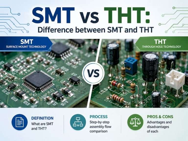
PCB assembly technology forms the core of virtually all electronic devices that we use today, ranging from mobile phones to computers to even automotive or medical electronics. How electronic components are assembled on a PCB will have an impact on how effective, reliable, costly, or compact the end product will be.
 
Two major types of PCB assembly technologies exist at the moment: Surface Mount Technology (SMT) and Through Hole Technology (THT). Although these two methods are quite critical to electronic assembly, they differ vastly in terms of the assembly process and many other aspects.
 
The purpose of this article is to provide a comparison between the two assembly methods, SMT and THT, and explore the differences between them.
SMT vs THT-Difference between SMT and THT

What is SMT?

Surface Mount Technology (SMT) is a process used in assembling Printed Circuit Boards whereby the electronic components are directly assembled onto the surface of the board. Unlike through-hole assembly process, the SMT process does not involve any hole drilling for mounting the component leads. Components which are referred to as Surface Mounted Devices (SMD) have solderable joints which connect to the copper joints on the PCB through the application of solder paste.
 
This allows mounting of electronic components on both sides of the PCB and also increases circuit density greatly compared to traditional processes. The benefits of this technology will be examined in a different part of the article.

Difference Between SMT and SMD?

Many people may occasionally refer to SMT and SMD as the same thing. But this is not true:
  • SMT (Surface Mount Technology) refers to the assembly process or technology used to solder components onto a board.
  • SMD (Surface Mount Device) refers to the actual component itself — such as resistors, capacitors, ICs, or LEDs — that is designed to be mounted using SMT.
 
If you would like to learn more about this topic, here is a separate blog entry we’ve created:

Typical SMT Assembly Process

The SMT process line is highly automated and, in fact, the line is designed to operate at high speeds, operate precisely, and produce consistent quality repeatedly. The following are the typical process steps for professional PCBA manufacturing:
 

Step 1: Solder Paste Printing

Stainless steel stencils are positioned over the bare PCB. Solder paste, which consists of solder particles and flux, is applied to the stencil, thereby applying precise quantities onto the copper pads where components are to be mounted.
 

Step 2: Pick & Place (Mounting Components)

A fast pick-and-place machine uses suction cups to extract the SMD components from reels or trays and places them into the precise locations on the solder paste dots. Modern pick-and-place machines have the ability to mount many components per second, with micron-level precision.
 

Step 3: Reflow Soldering

The board is then sent through a reflow soldering machine, which has several heating zones for preheating, soaking, reflow, and cooling. During the reflow stage, the solder melts, thus permanently attaching the terminals of the components to the circuit board pads.
 

Step 4: Automated Optical Inspection (AOI) & X-ray

Post-reflow inspection includes:
  • AOI, a test using high-quality cameras that detects any missing elements, misaligned components, bridging, or poor soldering.
  • X-ray inspection when joints cannot be seen, especially BGA and similar devices.
Note:
In case of double-sided SMT assembly, two inspections are carried out, with the first assembling the side where less weight is put and subsequently the other side. The reason is that it would protect the elements from falling off due to the heat produced through the reflow process.
 

What is THT?

Through Hole Technology, or THT, is one of the classic PCB assembly methods wherein the leads of the electronic component must first be pushed through the pre-drilled holes in the printed circuit board, after which soldering takes place on the copper pads on the other side of the board. This results in strong mechanical and electrical connections, making it suitable for components that are subjected to mechanical strain, high temperature, and high power.
 
Compared with SMT, THT involves drilling holes in the printed circuit board prior to assembly. In this method, the leads penetrate all the way through the board, while soldering is performed at the other end using wave soldering technique in the case of large volumes or manual soldering if only small quantities of products need to be made.
 
Although THT has largely been replaced by SMT for high-density, high-volume applications, it remains essential in specific use cases where durability, reliability, or manual rework capability is critical.

Typical THT Assembly Process

THT assembly can be either carried out manually or with the use of automatic equipment. The following is a brief description of the standard procedures that are followed during professional PCBA assembly for the through-hole components.
 

Step 1: Component Lead Preparation / Forming

For some through-hole components (such as resistors, capacitors, diodes), the leads supplied are usually long and straight. These leads have to be either bent or cut to the proper length and shape – referred to as “lead forming.” In some cases, the leads will have to conform to the hole spacing on the printed circuit board.
 

Step 2: Component Insertion

Component leads are inserted into the pre-drilled holes. This might be done:
  • Manual through operators (for prototypes, small runs)
  • Machine-operated (automatically) insertion using machines capable of mass production, mainly for standard component types like connectors, switches, and transformers.
 

Step 3: Wave Soldering

After all the components have been mounted, the circuit passes on to the wave soldering machine. On the under side of the printed circuit board, the waves of melted solder hit it. The solder flows through the holes of the circuit board and forms a good connection on the other end of it. If the circuit uses both the SMT and THT techniques, then the former is usually melted before soldering the latter with waves.
Hand soldering with the help of soldering iron: This process is usually employed only when manufacturing prototypes or in very small batches. The solder connections are made manually and with great precision.

Step 4: Trimming Excess Leads

After the soldering is completed, the extra leads of each component are cut with the help of lead-cutting tools. This prevents short circuits and saves space.
 

Step 5: Inspection

Inspection methods for THT assemblies include:

Summary

THT can be considered an ancient technology in comparison to SMT. However, it is still widely used today due to its importance in applications where components need to be securely attached, work at high temperatures, or just be easily replaceable. In fact, THT technology provides some advantages due to its relatively slow speed and dependency on hole size that cannot be achieved by SMT.

Advantages and Disadvantages of SMT

Surface mount technology forms the core of current electronics technology, though it has its distinct strengths and weaknesses.
 
The greatest strength of SMT technology lies in the fact that it uses relatively smaller and lightweight components. This means that there will be more functionalities within a limited area, as well as mounting the components on either side of the circuit board. The pick-and-place technology used in SMT makes it extremely economical since it reduces manufacturing costs. Moreover, the absence of holes for the components increases the electrical efficiency of the board.
 
However, there are some drawbacks associated with SMT as well. The solder joints produced with this technique are mechanically weak and prone to cracking when exposed to vibration, shock, or multiple thermal cycles. Heavy components, such as transformers or connectors, may come off the pads if the joint is not reinforced using an adhesive. Moreover, the procedure is extremely difficult, especially when it comes to fine-pitch components or BGA packages, since special equipment and highly qualified specialists are required. The cost of prototyping at the initial stage can be fairly expensive too (a stencil, programming). Finally, during reflow soldering, some components may get damaged due to high temperatures.
 
To sum up, SMT is the best choice in cases where a small footprint, large-scale production, and high performance are needed, whereas Through-Hole Technology will be more beneficial in other situations.
Pros & Cons of SMT and THT

Advantages and Disadvantages of THT

Although Through-Hole Technology precedes Surface Mount Technology in its invention period, it still retains its relevance, especially in situations where there is an increased risk of mechanical stress, as well as in instances where the assembly process is done manually.
 
The main advantages associated with THT are mechanical stability and ease of repairs, since some of the most important attributes such as strength against vibrations, power dissipation, and thermal stability arise from the hole in the printed circuit board through which the component pins can pass and get soldered on the other side. The ability to withstand mechanical stresses is why THT is normally preferred for connectors, transformers, heavy relays, and other components that are often touched and dissipate large amounts of heat. Additionally, THT assembly and removal can be easily performed manually, which greatly facilitates prototyping and repairs.
 
However, being a naturally bulkier and slower technology, THT not only occupies more room on the board but also weakens its structure to some extent due to the hole drilling. Component placement, whether done manually or using an automatic machine, is much slower compared to the SMT pick-and-place process. The wave soldering process along with the process of cutting the leads takes even more time and increases the cost of each board manufactured in volume production. Moreover, THT components are unable to be placed on both sides of the board, whereas their bulky nature prevents higher densities from being achieved in the circuit.
 
Essentially, THT is a speciality technology – useful when strength, power, and easy repair are required, but inappropriate when speed and bulkiness come into play. Thus, most commercially produced PCBs are usually manufactured using a combination of technologies, with SMT used for most of the components and THT only where necessary.

SMT vs THT: Key Differences Between SMT and THT

Although both Surface Mount Technology (SMT) and Through Hole Technology (THT) technologies are used to mount electronic parts on PCBs, these two differ in their design guidelines, mounting procedures, mechanical characteristics, and applicability. The differences are discussed in the table provided below.
FeatureSMT (Surface Mount Technology)THT (Through-Hole Technology)
Component mountingComponents placed on PCB surfaceComponent leads inserted through drilled holes
Holes requiredNoYes – holes drilled through the board
Component sizeMuch smaller and lighterLarger and heavier
Component leadsSmall pads or terminationsLong leads that pass through the board
Soldering methodReflow soldering (oven)Wave soldering or hand soldering
Assembly speedVery fast (automated pick & place)Slower (insertion, soldering, trimming)
Component densityVery high – components on both sidesLow – limited by hole spacing and lead access
Mechanical strengthModerate – relies on solder jointExcellent – leads anchored through the board
Thermal/mechanical stress resistanceLower – can crack under flex or repeated heat cyclesHigher – suitable for connectors, transformers, heavy parts
Rework & repairMore difficult (requires hot air, special tools)Easier – can be desoldered with basic tools
Prototype friendlinessHarder to hand-solder (small pitch)Easy to hand-solder
Cost for high volumeLower – faster, fewer stepsHigher – drilling, insertion, trimming add cost
Cost for low volume / prototypeHigher setup (stencil, pick & place programming)Lower – can be done manually
Typical applicationsSmartphones, laptops, tablets, high‑density consumer electronicsPower supplies, automotive modules, aerospace, large connectors

When to Use SMT vs THT?

There is no single “better” technology when choosing between SMT (Surface Mount Technology) and THT (Through-Hole Technology); the choice depends entirely on the specific needs of the project, including production scale, available board space, mechanical stress, power requirements, and maintainability.
 
Use SMT when:
When you need extremely high component density (e.g., smartphones, wearables, and IoT devices); when production scales reach thousands or even millions of boards; or when the design requires excellent high-frequency performance. Additionally, double-sided surface mount designs should also utilize SMT technology.
 
Use THT when:
When the design includes large components subjected to mechanical stress (e.g., large transformers, relays, connectors); when the board needs to undergo frequent thermal cycling or frequent insertion/removal operations. Furthermore, THT technology should also be used when it is easy to handle manually, or when the board needs to pass vibration testing and other environmental tests (e.g., military and aerospace applications).
 
The most common: Hybrid assembly
Most commercially produced PCBs rely on a combination of these two techniques. Design engineers will apply SMT for almost all components (resistors, capacitors, ICs, LEDs), leaving the exception of THT for connectors, larger electrolytic capacitors, switches, fuses, or any component that needs mechanical attachment. In hybrid assembly, the surface-mounting side is initially reflowed, while the through-hole side is then passed through the wave soldering process.
 
A basic principle:
  1. If it has to endure constant pulling, shaking, or plugging → THT.
  2. If it has to be compact, lightweight, and inexpensive in large quantities → SMT.
  3. Otherwise, assume SMT and resort to THT when needed.

Why Choose FS Tech PCBA Services for SMT and THT?

  • Multi-technology capabilities – Both SMT Assembly, THT Assembly, and mixed technology assembly on one PCB.
  • High-tech equipment – Pick-and-place machines, reflow soldering, wave soldering, AOI/X-Ray inspection.
  • Excellent quality control – AOI testing for SMT PCB; ICT testing for THT PCB.
  • Variable volumes – Prototype from 10 pieces to mass production above 50,000 pieces without MOQ.
  • One-stop solution – Both SMT and THT manufacturing in our PCBA factory, saving time and logistics fees.
  • Design support – FREE review and manufacturability suggestions.
  • Rapid delivery – Rapid prototyping and reliable delivery time on large orders.
 
Contact us today to discuss your next PCBA project or get a free quotation. We can help you choose your optimal combination of SMT and THT for the design.
🌍 Global PCBA · Full-Turnkey

Accelerate Global Launch
with Reliable PCBA

One-stop solution: PCB fabrication, sourcing, SMT assembly, testing & global logistics.
Fast turnaround, strict quality control.

⚡ Quick-Turn 5-7d 🏭 ISO13485 / IATF16949 ✈️ Worldwide Shipping
Contact Us →
⏱️ 24/7 expert consultation

Conclusion

SMT and THT do not compete – they work together. SMT offers high density, fast assembly, and low costs for mass production, which is why this technology makes up the foundation of modern consumer electronics. On the other hand, THT gives us enhanced mechanical durability, ease of manual handling, and good performance under duress, which is necessary in case of connectors, power components, and other critical elements.
 
Most real-world printed circuit boards take a mixed approach: SMT handles all the parts, while THT comes into play where necessary. It is up to you to decide based on your priorities.
 
Hopefully, this comparative overview helped you to make a sound choice regarding SMT vs THT. Should you have any further questions about combining both approaches on your board, don’t hesitate to contact us.

FAQs about SMT vs THT

Yes. Most modern PCBs are hybrid assemblies. The SMT side is typically reflowed first, followed by wave soldering or hand soldering for through‑hole components.
No. THT is still widely used for connectors, transformers, relays, electrolytic capacitors, and any component that must withstand mechanical stress or high heat. It also remains popular for prototypes and hobbyist projects due to easy hand soldering.
THT is usually cheaper for very small batches (e.g., 1–10 boards) because it requires no stencil or pick‑and‑place programming. For batches above 50–100 units, SMT becomes more cost‑effective
No. SMT (Surface Mount Technology) is the assembly process. SMD (Surface Mount Device) is the component itself. See our detailed post:
Consider these factors: board space, production volume, mechanical stress on components, need for rework, and high‑frequency performance. When in doubt, start with SMT and use THT only for heavy or frequently handled components. Our engineering team offers free design review — contact us.

Partner with us & Start your PBCA Project

Related Blogs